Power Control: DC Switch Bank
Updated:
Be careful to wire the switch connections correctly and make sure that the appliances you connect are compatible with the switches before wiring them in - in other words, your appliance should not pull more power than your switches can handle.
Youtube: googlevideo.com, youtube-nocookie.com.
Even if your build is "just a basic build", before you know it, you'll have wires coming out of every corner and hair falling out of your head, as you try to figure out what on earth is going on with this or that appliance. It was working yesterday and you didn't even touch it! I know. I've been there.
What you need is a switch panel. A central location for power control. Something like this:

Left: Charge controller remote panel, Right: DC switch panel (up to 5 circuits)
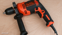
Mounting such a component is very simple. This one comes with four counter-sunk screw holes and a handful of screws. Since I wanted to mount this on my wooden divider, I started by marking the holes with a pencil and drilling the first one out to see how much wiggling would be needed to get the cable and switch to sit in the 18mm divider. "Quite a lot" was the answer.
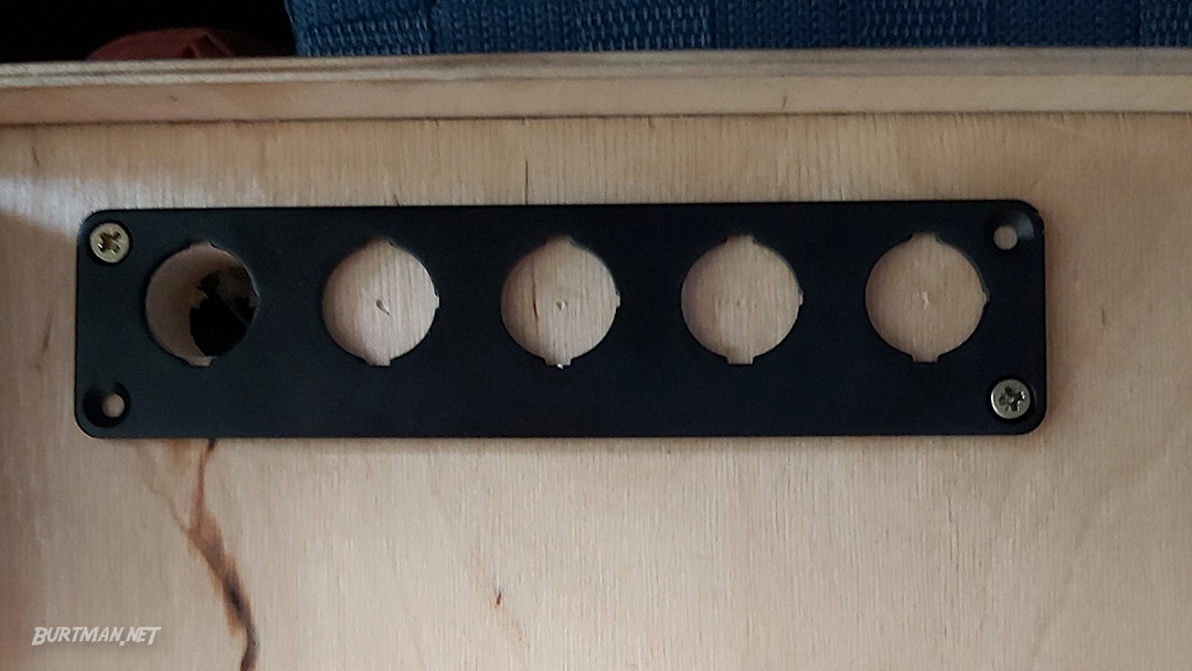
Once the first hole was finally cut wide enough for the switch to sit properly, I repeated the process for the other holes, wiggling the drill as necessary to create those diamondesque shapes. It's probably not the official method, but I'm not an official type of van-man - I do what works with what's available.

Yeah, I know. But nobody's gonna see that once the panel is fitted.
With the panel screwed in place, the switches are added. These switches can be confusing because they are DC switches but they have three connections on the back. That's because these switches have LEDs inside them that come on when the switch is in the ON position. I had to look this up, as all the DC switches I'd ever used previously had only had two connections. Here's a video that explains how they work:
You need to enable javascript from Youtube (and possibly others), in order to see this video.
You may want to use common positive and/or negative rails or similar, if you will be connecting multiple switches in one area. In that case, you can link all the positive connectors (gold pin) together and connect the last one to the battery + terminal, then do the same with all the negative connectors (opposite, silver pin) and connect the last one to the battery - terminal. Then, connect your DC device power to the center pin and top or bottom pin as in the video.
Common ground is where, instead of running every negative connection directly to the battery, which would be messy and difficult to manage, you just connect one cable to the battery and at the other end of that cable, you attach some kind of conductive connection, such as a rail or screw block. This way, all your connections just attach to that one cable. The same is true for positive. In case you didn't realize it, some devices in your van are wired to the body or frame of the van because the battery negative is also connected to the van's metal shell, so the van itself acts as the negative wire in all of those circuits.
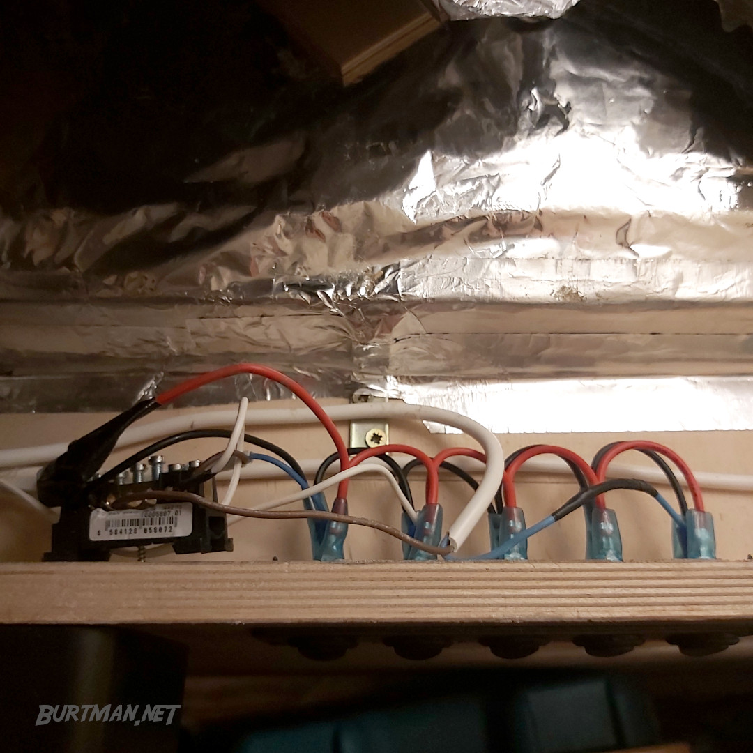
My common ground here is that screw block on the left. The white cable brings the power for the switches and all of the devices they control.
When you're finished, you've got switches that light up when switched on and devices that can be controlled from a single switch panel. Of course, you will need to take care of fuses as well, and you can find out about those here. In my case, the fuse box is mounted right next to where these device power cables run, so I just cut the cables and inserted the fuses inline. It's the neatest way in my particular layout and I have easy access to the fusebox right by the door. The fuses are, of course, rated according to the devices they power.
Sign In To Leave A Comment
There are no comments marked as public for this item.
Stay Up To Date



 Mark 4
 Read around 2,200 times
 For Everyone